How to Design Parts for FDM 3D Printing (Rules That Actually Matter)
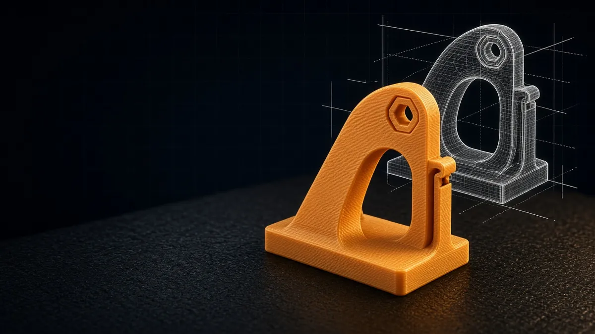
Designing parts for 3D printing means shaping a model around how an FDM printer builds it: one layer at a time, from a nozzle about 0.4 mm wide, with nothing underneath to hold up an overhang. Six rules decide whether a part prints well:
- Orientation first: FDM parts are weakest between layers, so lay the part out so the load runs along the layers and the largest flat face sits on the bed.
- Walls in whole lines: make walls a multiple of the extrusion width. With a 0.4 mm nozzle that is about 0.45 mm per perimeter, so 0.9 mm for two and 1.8 mm for four, according to Prusa's knowledge base.
- Overhangs up to about 45°: steeper faces and long bridges need support or a redesign. Chamfer downward-facing edges instead of filleting them.
- Clearance for anything that fits together: model a gap between mating parts. I usually design with 0.2 mm, but it depends a bit on the printer, so print a quick test first.
- Fillet the stress, chamfer the bed edge: round inside corners on load paths, and chamfer the first-layer edge to hide elephant's foot and reduce warping.
- Split what won't print flat: cut big or awkward parts into pieces that each print without support, and add pegs to line them up.
I design printable parts all the time. My Fenrir CoreXY and Ymir CrossXY printers are built from them, I release models on Patreon and Printables, and I write SindriCAD, a free parametric CAD app made for 3D printing. This guide is the checklist I work through. Where a number comes from somewhere else, such as Prusa's knowledge base or Protolabs Network's design guides, I name the source.
Updated 16 November 2026. The diagrams in this guide are illustrations made for it, not photos of my prints.
How should you orient a part for 3D printing?
Print orientation is the first design decision for any FDM part, because it decides which faces become overhangs, which direction the layer lines run and which face touches the bed. Pick it before you model the details, not after. Changing the orientation of a finished model often means redesigning half of it.
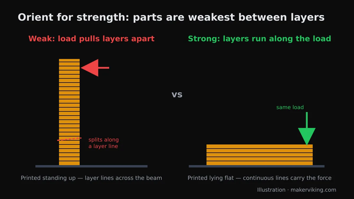
Like wood, FDM prints are stronger in one direction than another, as Prusa's knowledge base puts it. Protolabs Network's FDM design guide explains why: each layer joint is a small valley that concentrates stress, so a part loaded across its layers tends to crack along one of them. A few rules follow from that:
- Hooks, brackets and clips: print them on their side, so the bending load runs along the layers instead of trying to peel them apart.
- The biggest flat face goes on the bed: a surface printed on the bed is flat and smooth, while a surface printed above supports is rougher, according to Prusa.
- Holes follow the Z axis where possible: a vertical hole prints round without support. Protolabs Network notes that rotating a part 90° is often the easiest way to get rid of support in horizontal holes.
- Cosmetic faces stay off supports: keep the faces people will see away from support contact and from the layer seam.
When two requirements fight, for example strength wants one orientation and the looks want another, change the geometry or split the part so every piece can print in its best orientation. The splitting section below covers how.
How thick should walls be for 3D printing?
The minimum wall thickness for FDM printing is one extrusion line, but a practical wall is two lines or more. Prusa's knowledge base gives these approximate values for a 0.4 mm nozzle, which PrusaSlicer prints with a 0.45 mm extrusion width:
| Perimeters (0.4 mm nozzle) | Wall thickness | Use it for |
|---|---|---|
| 1 | about 0.45 mm | Vases and decorative shells only |
| 2 | about 0.9 mm | Light covers, boxes and enclosures |
| 3 | about 1.35 mm | General parts |
| 4 | about 1.8 mm | Load-bearing walls and screw bosses |
The exact widths vary with slicer settings, so treat the table as a guide, not a spec.
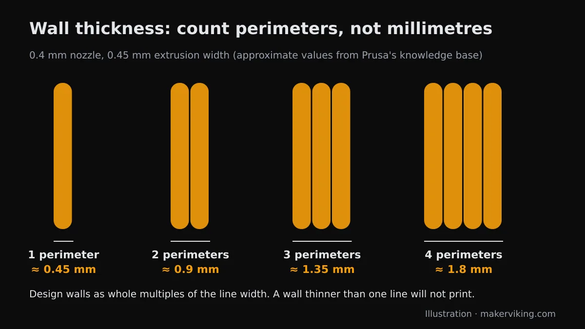
Design walls as whole multiples of your line width. A wall that falls between two line counts forces the slicer to squeeze in a thin gap-fill line or vary the line width. Current slicers handle that better than old ones, but whole multiples are still the predictable choice. Prusa is blunt about the lower limit: walls thinner than one perimeter are not printable, and its slicer's "Detect thin walls" option can't repair them.
The same logic applies to small features:
- Fine details: anything narrower than one line, such as a 0.3 mm rib on a 0.4 mm nozzle, simply disappears. Make raised text and ribs at least one line wide, and preferably 2x the line width.
- Small pins: Protolabs Network's FDM design guide says pins under 5 mm in diameter print as perimeters with no infill and can snap off. Add a fillet at the base, or print a hole and press in a metal pin.
- Bigger nozzles: scale everything with the nozzle. A 0.6 mm nozzle lays wider lines, so its minimum wall and feature sizes grow with it.
When do overhangs need support?
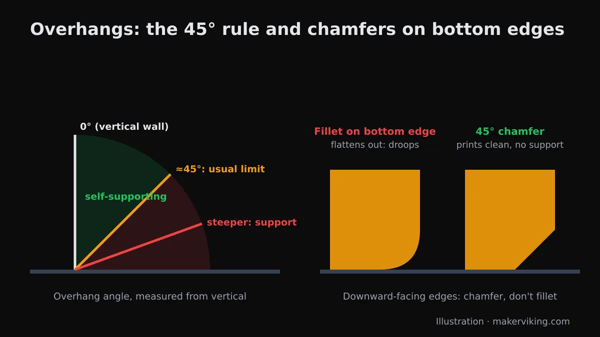
An overhang is any face that leans out past the layer below it, and the usual rule of thumb is that FDM printers handle about 45° from vertical without support. Protolabs Network's FDM design guide explains the number: at 45°, each new layer still rests on 50% of the layer below. Prusa's knowledge base gives a range of 45–60° depending on nozzle and settings, and says its Nextruder printers with 360° cooling can reach 75°. Smaller nozzles, such as 0.25 mm, manage less.
A bridge is a horizontal span between two supports, like the roof of a hole in a wall. Protolabs Network says some sag or support marks are almost always present unless the bridge is shorter than 5 mm. Longer bridges can print well with good cooling, but test them before you rely on them.
Redesign before you add supports
Designing supports out is almost always better than printing them, because supports cost time and filament and leave marks on the surface. These are the fixes I reach for first:
- Chamfer downward-facing edges: a fillet facing the bed turns into a very steep overhang at its lower end, so Prusa recommends a chamfer where the finish matters.
- Reshape horizontal holes: a teardrop or flat-topped hole is self-supporting where a round one needs support at the top.
- Use arches and 45° slopes: under a shelf, a 45° gusset or an arch prints on its own and adds strength.
- Split the part: two pieces that each print flat beat one piece covered in supports.
- Move the overhang underneath: flip the part so the overhang becomes a face sitting on the bed.
Supports are fine when the face is hidden, when the part is a one-off prototype, or when the model is organic, like a sculpted figure, where tree supports are usually the only realistic option.
What tolerance should you use for 3D printed parts?
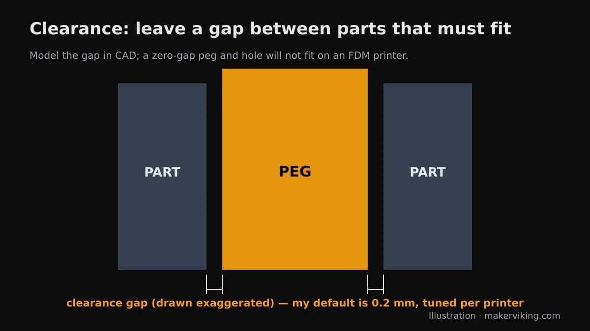
Clearance is the gap you model between two parts that have to fit together, and you always need one: a zero-gap peg will not go into a zero-gap hole on an FDM printer. There is no universal value. Prusa's knowledge base lists model size, orientation, the geometry of the interlocking parts, calibration, slicer settings and material as the factors that change it.
My default clearance is 0.2 mm. That's what I usually design with, but it depends a bit on the printer, so I treat it as a starting point, not a law. On a new printer or a new filament, print a small test with the same peg in holes at a few clearances around it, and keep the smallest gap that assembles the way you want.
| Fit | Starting clearance | Source |
|---|---|---|
| Parts that slot together | 0.2 mm, then test | My usual default, printer-dependent |
| Moving parts such as hinges | at least 0.3 mm | Prusa's knowledge base |
| FDM snap-fit joints | 0.5 mm | Protolabs Network |
Holes
Vertical holes are usually undersized when printed. Protolabs Network explains that the nozzle squashes each line wider as it presses it down, which shrinks the hole, and the effect is worst on small holes. If a hole size is critical, print it slightly undersized and drill or ream it to size. The first layer also flares out into "elephant's foot", so a chamfer on the bottom of holes and outer edges, or the slicer's elephant foot compensation, keeps fits right at the base.
Threads and fasteners
Printed threads are fine for large, coarse threads such as jar lids, but small machine screws need something stronger than plastic threads:
- Heat-set inserts: brass inserts melted into a modelled hole, for screws you will remove and refit.
- Captive nuts and nut bars: a hexagonal pocket or a slot that holds a nut or a metal bar. On Fenrir I replaced the heat inserts for the Y-axis linear rails with a nut bar, which made it easier to build and a bit more rigid.
- Self-tapping into plastic: fine for screws you rarely remove.
Snap-fits
A snap-fit is a joint where a flexible hook or bead on one printed part clicks into a recess on the other, so you need no screws at all. Protolabs Network's snap-fit guide recommends:
- Taper the beam: make it thinner towards the tip so the strain spreads out.
- Fillet the root: use a radius of at least 0.5 times the base thickness.
- Keep it wide: make the clip at least 5 mm wide.
- Don't print it standing up: avoid cantilevers built along the Z axis, because the layers make them weak in that direction.
- Use a tough material: pick ABS, PETG or nylon over brittle PLA, with about 0.5 mm clearance on FDM.
Should you use fillets or chamfers on 3D printed parts?
Fillets are better on inside corners and on edges that face up or sideways, whereas chamfers are better on edges that face down onto the bed. A sharp inside corner concentrates stress, so a fillet there makes the part stronger. On a bottom edge, the same fillet becomes an overhang that droops.
Protolabs Network's FDM design guide adds two details. Because the nozzle is round, printed corners are never perfectly square: they get a radius about the size of the nozzle. And a 45° chamfer or radius on every edge touching the build plate reduces elephant's foot and warping and makes the part easier to remove. Prusa points out that a chamfer on the edges of parts that slot together also makes assembly much easier.
Designing against warping
Warping is a part's corners lifting off the bed as the lower layers cool and shrink, and ABS is more prone to it than PLA because of its higher printing temperature. Good print settings help, and my guide to warping causes and fixes covers them, but the design matters too:
- Round the corners of the footprint: sharp corners lift first, and a radius in the plan view spreads the pull.
- Avoid big, solid, flat bases: hollow them out or use ribs where you can.
- Chamfer the bottom edge: it hides any first-layer flare as well.
- Leave room for a brim: keep tiny features away from the base edge so a brim can be peeled off cleanly.
How do you split large parts for 3D printing?
Splitting a model means cutting it into pieces that each print in their best orientation and then joining them, and it is the standard fix for parts that are too big for the bed or impossible to print without heavy support. Prusa's knowledge base says splitting improves both the looks and the mechanical properties of a model, and Protolabs Network notes it can remove supports altogether.
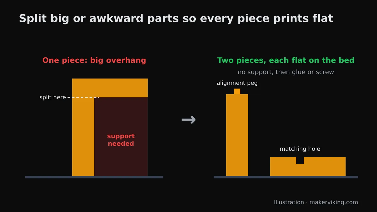
Splitting is exactly what I did on Fenrir in 2022, when I split each main section of the printer into two parts to make them easier to print with fewer supports, and as a bonus that made contrast colours possible. When you split a part:
- Split along a flat face: each piece should get a big flat face to sit on the bed.
- Add alignment features: pegs and holes, with your normal clearance, line the pieces up. Prusa also suggests pegs to add strength to glued joints.
- Pick the joint: glue for permanent joints (on clean, lightly sanded surfaces, according to Prusa), screws with nut traps for parts you'll take apart, or dovetails for a tool-free fit.
- Hide the seam: place splits along existing edges or details. If you'll paint the part, my tips on painting 3D prints cover filling and priming seams.
Your printer's build volume decides how often you have to split. If you're still choosing a printer, 3D printer specifications explained covers build volume and the other specs that matter for big parts.
How do you design for PLA, PETG, ABS and TPU?
The material is part of the design, not just a print setting. A clip that works in PETG can snap in PLA, and a part that's fine in PLA on a desk can sag in a hot car. Prusa's knowledge base makes the general point that tough outdoor materials such as PC, ASA and PETG don't print small details as well as PLA, so avoid fine details on parts meant for outdoor use or mechanical strain.
| Material | Design for | Watch out for |
|---|---|---|
| PLA | Detail, prototypes, stiff parts, miniatures | Brittle in thin flexing features; Prusa says it softens above 60 °C |
| PETG | Clips, snap-fits, functional and outdoor parts | Tougher than PLA and rated below 80 °C by Prusa; strings more and doesn't hold fine detail as well |
| ABS / ASA | Heat-resistant and enclosure parts | Warps more than PLA, so use rounded footprints, chamfers and an enclosed printer |
| TPU | Gaskets, feet, bumpers and grips | Flexible, so design thicker walls, avoid tiny details and long bridges, and print slowly |
For more on each material, see my complete guide to 3D printing filaments and the PLA vs PETG comparison. If you plan to combine materials in one part, the filament compatibility chart on TinkerAtlas shows which pairs bond.
How do you design for multi-colour and toolchanger printers?
Designing for multi-colour printing means modelling each colour or material as its own solid body, so the slicer can assign each body to a filament. Prusa's knowledge base notes that the slicer can take each colour as a separate file or as several objects in one 3MF file, and that every body has to be a closed, manifold solid on its own.
How you design also depends on the kind of multi-colour printer:
- Single-nozzle filament changers such as an AMS purge filament at every colour change, so the number of changes drives the waste. Fewer colour changes per layer, and colours grouped by height, save filament. My toolchanger vs AMS guide compares the methods.
- Toolchangers such as the Snapmaker U1 keep each filament in its own heated toolhead. The U1 has four, and Snapmaker lists a swap time of about 5 seconds. Lab test data from Snapmaker, published on its U1 product page, shows up to 85% less filament waste than a shared-nozzle printer on the same multicolour models. The U1 still prints a small prime tower but skips the big purges, and it can combine materials that need different temperatures, such as PLA with TPU, or PLA with soluble PVA support.
A toolchanger opens up designs that are hard on a single nozzle: a rigid part with a printed-in flexible grip, or internal overhangs supported by PVA that you dissolve away afterwards. Check that the materials actually bond before you design around them. I use a U1 for multi-colour work. If you're choosing between it and a single-colour machine, my Snapmaker U1 vs Bambu Lab P2S comparison explains why I pick the U1 for multi-colour and the P2S for single-colour printing.
My workflow: SindriCAD, export, then OrcaSlicer
My design workflow for printed parts is five steps from parametric CAD to a test print:
- Sketch with named parameters. I model in SindriCAD, my free parametric CAD app (it won a $1,500 third prize in Snapmaker's U1 Innovation Fund in 2026), and keep key values like the clearance as named parameters. Moving to a printer that needs a different fit is then one number, not a redraw.
- Model in the print orientation. Deciding which face goes on the bed while modelling keeps overhangs and layer direction in view. SindriCAD's measure and section tools check wall thickness and clearances before export.
- Export the right format. STEP is for passing the model to other CAD tools. 3MF is best for slicing, because it keeps units and several bodies and colours in one file. STL works everywhere but is a bare mesh with no units.
- Slice and check the preview. SindriCAD can open a U1 project straight in OrcaSlicer. In any slicer, the preview shows thin walls that vanish and overhangs that need support before you waste filament. My OrcaSlicer vs PrusaSlicer vs Cura comparison and slicer settings guide cover the slicer side.
- Print a test section, then adjust. I print just the fit or the critical feature, change the parameter and reprint. That fast loop is what rapid prototyping on a 3D printer is all about.
SindriCAD is free for Linux, Windows and macOS at tinkeratlas.com/sindricad. If you're weighing it against other free CAD, see SindriCAD vs FreeCAD on TinkerAtlas. Before any of this, make sure the printer itself is dialled in, because no design rule survives a badly calibrated machine. My list of first things to 3D print on a new printer starts with the calibration prints.
Worked examples
Worked examples are where the rules meet real parts. The first two are a case study in fixes I made on my own Fenrir printer, and the last two show how I'd apply the checklist to everyday parts.
Case study: Fenrir's split sections
Splitting is how I made Fenrir's main printed sections easier to print in 2022. Splitting each one into two parts, with the smaller part of each section at the back, made them easier to print with fewer supports. It also made contrast colours easy, since each half can be a different filament. The cost of any split is a joint you have to align and fasten, which is why the alignment features matter.
Case study: Fenrir's nut bars
A nut bar is a metal bar with threaded holes that sits in a printed slot. In September 2023, for Fenrir's Y-axis linear rails, I replaced the heat-set inserts with a nut bar, which the Z-axis rails already had. That made the printer easier to build and a bit more rigid. The lesson is that the best fastener for a printed part is often a metal part the plastic simply holds in place.
A wall bracket
A wall bracket is a good test of all the rules at once. For a simple L-shaped shelf bracket, I'd print it on its side, so the bending load runs along the layers. I'd add a fillet on the inside corner where the stress concentrates, a 45° chamfer on the edges that touch the bed, countersunk screw holes along the Z axis so they print round, and walls of three or four perimeters. In PETG it will flex a little before it fails, and in PLA it will be stiffer but more brittle.
A box with a press-fit lid
A press-fit lid is where clearance matters most. I start the lip at my 0.2 mm clearance, chamfer the lip's leading edge so it finds its way in, and print a thin ring of just the lip and the box rim before committing to the whole box. If the ring is too tight or too loose, I change the clearance parameter and reprint the ring. That takes minutes, not hours.
If a print still fails after all this, my list of 30 common 3D printing problems and their solutions separates design problems from printer problems.
FAQ
What is the best orientation for 3D printing a part?
The best orientation for 3D printing is the one that runs the main load along the layers, puts the largest flat face on the bed and keeps overhangs under about 45°. When those goals conflict, split the part so each piece can print in its best orientation.
How thick should walls be for 3D printing?
Minimum wall thickness is about 0.45 mm, one perimeter, with a 0.4 mm nozzle, and practical walls are 0.9–1.8 mm, two to four perimeters, according to Prusa's knowledge base. Design walls as whole multiples of your line width.
What clearance should I use for 3D printed parts?
A good starting clearance is 0.2 mm, which is what I usually design with, but the right value depends on the printer, material and orientation. Prusa suggests at least 0.3 mm for moving parts, and Protolabs Network suggests 0.5 mm for FDM snap-fits. Print a quick test to dial it in.
What is the maximum overhang angle without supports?
The maximum overhang angle without supports is about 45° from vertical on most FDM printers. Prusa's knowledge base gives 45–60° depending on nozzle and settings, and up to 75° on its printers with 360° cooling.
Should I use fillets or chamfers on 3D printed parts?
Chamfers are the better choice on edges that face the build plate, because a fillet there becomes a steep overhang. Fillets are better on inside corners and upward-facing edges, where they reduce stress concentration and look cleaner.
What file format should I export for 3D printing?
The best export format for 3D printing is 3MF, because it keeps units, several bodies and colour assignments in one file. STL works in every slicer but has no units or colours. Keep a STEP copy for editing in other CAD tools.
What software is best for designing 3D printable parts?
Parametric CAD is the best kind of software for functional printed parts, because you can change one dimension, such as a clearance, and the whole model updates. SindriCAD is my free, open-source option built for 3D printing, and FreeCAD is another free choice. Sculpting tools suit organic models like figures.
Sources
Sources were checked on 16 November 2026.
- Prusa Knowledge Base: Modeling with 3D printing in mind
- Protolabs Network: How to design parts for FDM 3D printing
- Protolabs Network: How do you design snap-fit joints for 3D printing?
- Prusa Knowledge Base: PLA and PETG (temperature limits)
- Multicolour 3D printing: toolchanger vs AMS (Snapmaker U1 toolhead facts)